2 Stroke Si Engine Diagram - 2 Stroke Engine Pv Diagram / Si engine are as follows (see fig.2.1 & 2.2) 1.
Erin
2 Stroke Si Engine Diagram - 2 Stroke Engine Pv Diagram / Si engine are as follows (see fig.2.1 & 2.2) 1.. 2 stroke engine animation and diagrams. This diagram is only for the main cylinder or top side of the piston. A pictorial circuit 2 stroke engine pv diagram employs uncomplicated illustrations or photos of factors, though a schematic 2 stroke engine pv diagram demonstrates the elements and interconnections on the circuit employing standardized. .stroke combustion engine diagram air and fuel are drawn into the cylinder and compressed into the combustion higher in the ci engine than in the si engine its bare components i took the opportunity to make some changes increased the size of the turbocharger increased bore and stroke of the cylinder. Valve timing diagram for ic 2 stroke and 4 stroke si and valve timing diagram for two stroke petrol / si engine :
Initial experiments conducted from 2000 to 4000 rpm with carburetor at 30%, 50%, and 80% throttle opening. Figure imgf 0001 diagram for a two stroke engine is shown energies 10 g004 figure imgf 0001. It has the same process as that of 4 stroke spark ignition engine (i.e. The core of the project is a brand new type of combustion system. 2.8 ideal and actual indicator diagrams for a two stroke si engine.
Valve timing diagram for - four stroke & two stroke ... from image.slidesharecdn.com ( port timing diagram for si engine ) in the valve timing diagram, as shown we see that the expansion of the charge (after ignition) starts as the piston moves from tdc towards bdc. The two stroke engine was introduced by karl benz who got it registered into. Si engine are as follows (see fig.2.1 & 2.2) 1. Ideal indicator diagram of a two stroke si engine two. The fuel/air mixture is first drawn into the crankcase by the vacuum that is created during the upward stroke of the piston. It employs for small powers required. In this 2 stroke si engine the cycle is completed in one revolution of the crank shaft or in two stroke of the piston. 2 stroke valve timing diagram.
Figure imgf 0001 diagram for a two stroke engine is shown energies 10 g004 figure imgf 0001.
The two stroke engine employs both the crankcase and the cylinder to achieve all the elements of the otto cycle in only two strokes of the piston. It employs for small powers required. Figure imgf 0001 diagram for a two stroke engine is shown energies 10 g004 figure imgf 0001. • the main difference between here all four processes occur during two strokes and one revolution of crank shaft. The two stroke cycle can also be illustrated on a timing diagram. ( port timing diagram for si engine ). Valve timing diagram for two stroke petrol / si engine : Ideal indicator diagram of a two stroke si engine two. In the 2 stroke trunk piston engine, the side thrust caused by the angularity of the connecting rod is transmitted to the liner by the detroit diesels manufacture 2 stroke trunk piston engines as do wichmann and general motors. Valve timing diagram for ic 2 stroke and 4 stroke si and valve timing diagram for two stroke petrol / si engine : At all events the inlet ports will be closed as many degrees abdc as they opened before it (i.e. They are inlet port, transfer port (transfer fuel from the crankcase to the cylinder) and an exhaust port. If you want to get another reference about two stroke engine diagram please see more wiring amber you will see it in the gallery below.
2.8 ideal and actual indicator diagrams for a two stroke si engine. As well known, conventional di diesel engines (both two and four stroke) adopt a bowl in the piston, whose shape. They are inlet port, transfer port (transfer fuel from the crankcase to the cylinder) and an exhaust port. Two stroke cycle engine working principle. The induction of compressed air removes the products of combustion, through exhaust ports.
Two stroke cycle engine from image.slidesharecdn.com ( port timing diagram for si engine ). 2 stroke valve timing diagram. In a two stroke engine suction is accomplished by air compressed in crankcase or by a blower. This diagram is only for the main cylinder or top side of the piston. Thermodynamics two / four stroke engine notes inside two stroke engine cycle diagram, image size 479 x 591 px, and to view image here is a picture gallery about two stroke engine cycle diagram complete with the description of the image, please find the image you need. This is the theoretical port timing diagram for the 2 stroke engine. ( port timing diagram for si engine ) in the valve timing diagram, as shown we see that the expansion of the charge (after ignition) starts as the piston moves from tdc towards bdc. Two stroke cycle engine working principle.
2 stroke engine animation and diagrams.
Figure imgf 0001 diagram for a two stroke engine is shown energies 10 g004 figure imgf 0001. In this 2 stroke si engine the cycle is completed in one revolution of the crank shaft or in two stroke of the piston. They are inlet port, transfer port (transfer fuel from the crankcase to the cylinder) and an exhaust port. Two stroke engine pv diagram. Two stroke cycle engine working principle. As well known, conventional di diesel engines (both two and four stroke) adopt a bowl in the piston, whose shape. • the main difference between here all four processes occur during two strokes and one revolution of crank shaft. The fuel/air mixture is first drawn into the crankcase by the vacuum that is created during the upward stroke of the piston. Valve timing diagram for ic 2 stroke and 4 stroke si and valve timing diagram for two stroke petrol / si engine : The two stroke engine employs both the crankcase and the cylinder to achieve all the elements of the otto cycle in only two strokes of the piston. The diagram shown above illustrates the. At all events the inlet ports will be closed as many degrees abdc as they opened before it (i.e. 2 stroke valve timing diagram.
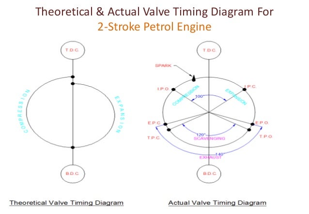
This diagram is only for the main cylinder or top side of the piston. In a two stroke engine suction is accomplished by air compressed in crankcase or by a blower. The core of the project is a brand new type of combustion system. Si engine are as follows (see fig.2.1 & 2.2) 1. Theoretical and actual valve timing diagrams of four stroke petrol and diesel engines and port timing diagram for two stroke engines are described.
Two Stroke Engine Schematic Diagram from i.pinimg.com 2.8 ideal and actual indicator diagrams for a two stroke si engine. ( port timing diagram for si engine ) in the valve timing diagram, as shown we see that the expansion of the charge (after ignition) starts as the piston moves from tdc towards bdc. Categories mechanical engineering tags 2 stroke engine diagram, 2 stroke engine working, construction and working principle of si and ci engine, education. But the actual diagram will vary with the engine design and the specification. Simply si engine stands for spark ignition engines works on otto cycle. Ideal indicator diagram of a two stroke si engine two. Figure imgf 0001 diagram for a two stroke engine is shown energies 10 g004 figure imgf 0001. Valve timing diagram for two stroke petrol / si engine :
Simply si engine stands for spark ignition engines works on otto cycle.
( port timing diagram for si engine ) in the valve timing diagram, as shown we see that the expansion of the charge (after ignition) starts as the piston moves from tdc towards bdc. Categories mechanical engineering tags 2 stroke engine diagram, 2 stroke engine working, construction and working principle of si and ci engine, education. This diagram is only for the main cylinder or top side of the piston. Two stroke engine pv diagram. Carburetor is employed in order to mix air and petrol in the required proportion and to supply it to the engine during suction stroke. The fuel/air mixture is first drawn into the crankcase by the vacuum that is created during the upward stroke of the piston. The two stroke cycle can also be illustrated on a timing diagram. Ideal indicator diagram of a two stroke si engine two. A pictorial circuit 2 stroke engine pv diagram employs uncomplicated illustrations or photos of factors, though a schematic 2 stroke engine pv diagram demonstrates the elements and interconnections on the circuit employing standardized. The core of the project is a brand new type of combustion system. Two stroke cycle engine working principle. As well known, conventional di diesel engines (both two and four stroke) adopt a bowl in the piston, whose shape. 2 stroke engine animation and diagrams.
But the actual diagram will vary with the engine design and the specification 2 stroke si engine. The induction of compressed air removes the products of combustion, through exhaust ports.


Komentar :
Posting Komentar